This post is, once again, coming to you from Joraaver.
Last time, I talked about how the stages of our game are designed in Tiled, and what layers we had to look for. I also addressed leveraging the SAX parser in Java to parse the tmx file for the objects.
Today, I'm going to analyze how I stored my objects from Tiled and how I mapped them as tiles to jME's coordinate plane.
Most of the information regarding the "gid" number of the tile and collecting tilesheets is in the Parsing and Rendering TMX Files tutorial by GameDev Tuts+. I'll only be covering the things that are jME specific, and will touch base on the "gid" information if necessary.
Collecting the Objects
First, I'll quickly dive into collecting the tilesheets. Follwing the tutorial above, I created a nice and simple TileSet class, with the same attributes. Then, inside the DeafaultHandler I created, the code below handles grabbing each tileset and creating an instance for it:
public void startElement(String uri, String localName,String qName, Attributes attributes) throws SAXException {
  if(qName.equalsIgnoreCase("tileset")){
      firstgid = Integer.parseInt(attributes.getValue("firstgid"));
      tileset_name = attributes.getValue("name");
      tileset_tile_width = Integer.parseInt(attributes.getValue("tilewidth");
      tileset_tile_height = Integer.parseInt(attributes.getValue("tileheight"));
  }
  if(qName.equalsIgnoreCase("image")){
      tileset_image_path = "Textures/"+attributes.getValue("source");
      tileset_image_height = Integer.parseInt(attributes.getValue("height"));
      tileset_image_width = Integer.parseInt(attributes.getValue("width"));
      tilesets.add(new TileSet(firstgid,tileset_name,tileset_tile_width,
                         tileset_tile_height,tileset_image_path,tileset_image_width,tileset_image_height));
      total_tilesets++;
  }
  ...
}
First, there is an image group for the tilesheet, which provides the firstgid of each tilesheet, and then the tileset group, which provides the information specific to that sheet. If we look at sample line from my one of my tmx files:
<tileset firstgid="2" name="tilesheet" tilewidth="32" tileheight="32">
    <image source="Tiles/tilesheet.png" trans="ff00ff" width="64" height="32"/>
 </tileset>
The tileset's firstgid is 2, and each tile in it is 32x32 pixels. The source of this tile is in "Tiles/tilesheet.png" and its size is 64x32, indicating there is 1 row of 2 tiles.
The concept of a gid is explained well in the tutorial I linked to at the start, so I won't be explaining it here.
The Floor layers objects are simply gids stored in a Vector.
For my objects that were in my Node and Collision layers, I followed the same process, except here, I only stored the x, y, width, and height of each object.
From here on out, the tutorial handles it pretty well, so I'm going to talk about what I had to change to make the map work with jME.
Rendering the Tiles on the Screen
Just like the tutorial, I was able to make a simple image as a map. However, that didn't leave me with a way to individually generate collisions for the tile, so I wanted the approach to be tile based.
Thus, I turned to this set of steps:
1) Create a BufferedImage of the tile's width and height.
2) Fill in the image with the tile's pixel values (RGB).
3) Create a 1x1 quad.
4) Create a Geometry for that quad.
5) Create a Texture2D from the image.
6) Create a Material from that texture.
7) Set the geometry's material.
8) Create a Node, and set it's name to "invisible" if the tile was transparent.
9) Attach the geometry to that Node.
10) Set the translation (location) of the tile relative to the screen.
11) Add it to the level.
This seems like a lot of steps, but steps 3 through 7 are standard issue for any Geometry, and are pretty simple. The code for steps 1, 2 and 10 is difficult, so here is the code I used:
//Step 1
BufferedImage tile = new        BufferedImage(getTile_width(), getTile_height(),    BufferedImage.TYPE_INT_ARGB);
//Step 2
tile.setRGB(0,0, current.getTile_width(),current.getTile_width(), ((BufferedImage)tilesetImages.get(current_counter)).getRGB(source_x*current.getTile_width(), source_y*current.getTile_height(), current.getTile_width(), current.getTile_height(), null,0, current.getTile_width()), 0, current.getTile_width());`
setRGB accepts the x, y of where to start filling from, the width and height to fill up to, and the array of pixels to fill from. In order to set this array of pixels, I had to use getRGB on the tilesheet, with the same parameters. The tough part was the "offest" and "scansize" parameters (the last two of setRGB and getRGB), simply because I didn't understand them. I'm sorry I can't give a more in depth explanation, but after fiddling around, these values worked for me.
//Step 10
quad_tile.setLocalTranslation(dest_x/32f,((getMap_height()*getTile_height())-dest_y)/32f,0f);
The dest_x and dest_y are the placement of the tile, in pixels. The division by 32 (it shouldn't be hardcoded; rather, it should be getTile_width() and getTile_height()) can be demonstrated by this well drawn picture:
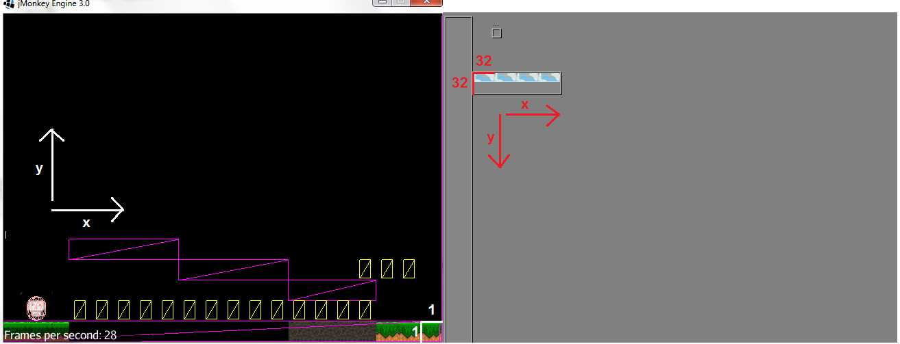
Since I map the each 32x32 tile to a 1x1 quad, I have divided each tile by 32, reducing it to 1x1. This is simply a linear transformation (if you know your linear algebra, this is an eigenvector on the coordinates of each tile, where lambda = 1/32)
The other issue is that the y axis is flipped. jME works from the bottum up, but Tiled works from the top down. Thus, I had to take the map's height (in tiles), mulitply it by the tile's height, and then subtract the dest_y from it. This returns the pixel height from the bottom of the image. Now, dividing by the tile's height gives me its coordinates on the screen in jME.
I'm almost done now. I've got the tiles in the right place, now I just need the physics boxes.
Placing the Physics Objects on the Screen
The process here is almost the same as the tile process. The difference is the width and height of the screen won't be the same as the width and height of the map from Tiled, so some scaling must be done.
So, iterating through each object in the Collision Layer, I have this code:
x = (x/32f)  * ((cam.getFrustumRight()-cam.getFrustumLeft())/rxf.getMap_width());
y = (rxf.getMap_height() -(y/32f)) * (cam.getFrustumTop()-cam.getFrustumBottom())/rxf.getMap_height();
w = w/32f * ((cam.getFrustumRight()-cam.getFrustumLeft())/rxf.getMap_width());
h = h/32f * ((cam.getFrustumTop()-cam.getFrustumBottom())/rxf.getMap_height());
RigidBodyControl floorMesh = new RigidBodyControl(new BoxCollisionShape(new Vector3f(w/2f,h/2f,1)),0.0f);
The same process is done to transform the coordinates. The new part is the use of the camera's frustum. In order to keep everything consistent, I defined what the top and bottom frustum of the camera were, and then, based on the original ratio of top frustrum to right frustum, set the left and right frustum of the camera. Thus, my map's height became cam.getFrustumTop() - cam.getFrustumBottom() (top is positive, bottom is negative) and width became cam.getFrustumRight() - cam.getFrustumLeft(). Then, the multplication factor for each of the coordinates simply became my map's width and height over the original map's width and height.
Then, to place the physics objects (after creating the RigidBodyControl), I had to do a little more math:
floorMeshNode.getControl(RigidBodyControl.class).setPhysicsLocation(new Vector3f(x-cam.getFrustumRight()+w/2f,y-cam.getFrustumTop()-h/2f,-2));
The issue is, (0,0) on the screen is in the center of the screen, not in the lower left. So I had to subtract half the width and height of my map and then shift the object over by half its width and height to place it in the right point. Each quad of the tiles has its (0,0) at the bottom left, but the RigidBody's center is in the middle of its width and height, which must accounted for by the above actions.
The objects in the Nodes layer follow the same steps, as well as the GhostControls I have above for the tiles labeled "invisible."
Contemplations
Boy, that was a long and meaty post. But, before I finish, a few things to think about.
I had an issue where small black holes would appear in the middle of my RigidBodies (my physics boxes), showing up on top of the tiles. To understand the issue, a crude picture:
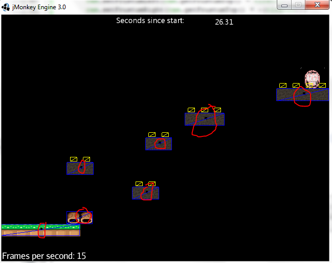
After some digging, it's seems like textures on quads with physics boxes bigger than it's own size (in the z axis) don't agree. To fix this, I had to place all my quads in front of my RigidBodies. This gives the illusion that my player is on the tiles, even though the tiles and the RigidBodies exist on different planes along the z axis.
As far as I know, 2D games in jME using Tiled are scarce. In fact, some people on the forums suggest that jME is too powerful for the needs of such a simple game in terms of physics. However, I decided to use this approach because I like jME, and I believe both 2D and 3D games can be produced by this engine. Unity used to be a 3D specific platfrom, but as more people began using it for 2D, Unity eventually came out with a 2D framework.
In other words, be the change you want to see in the world.
Thanks for following through with this 1400 word post. If you have any questions, just email me at indiebynight at elrel dot com and I'll be sure to answer it.